Structural FEA, CFD and particle-flow simulation, hazardous-area studies and full design support, shown with the industries we serve and the projects we have delivered.
SIMULATION
FEA, CFD and particle flow
Three disciplines, often combined in one study: particle loads into FEA, airflow into heat transfer.
Structural FEA for tanks, vessels and machinery
We build the finite element model from a hand-calculated basis, apply the real loads and supports, check mesh convergence and assess the results against the governing code, not just a colour plot.
Storage tanks and silos: hydrostatic, wind, seismic, roof and nozzle loads
Pressure vessels: design by analysis, local nozzle and support stresses
Buckling of thin shells, roofs and frames under vacuum or external load
Fatigue life of welded joints under cyclic pressure or vibration
Modal and harmonic analysis of rotating equipment and skids
Thermal stress from start-up, CIP and hot-product cycles
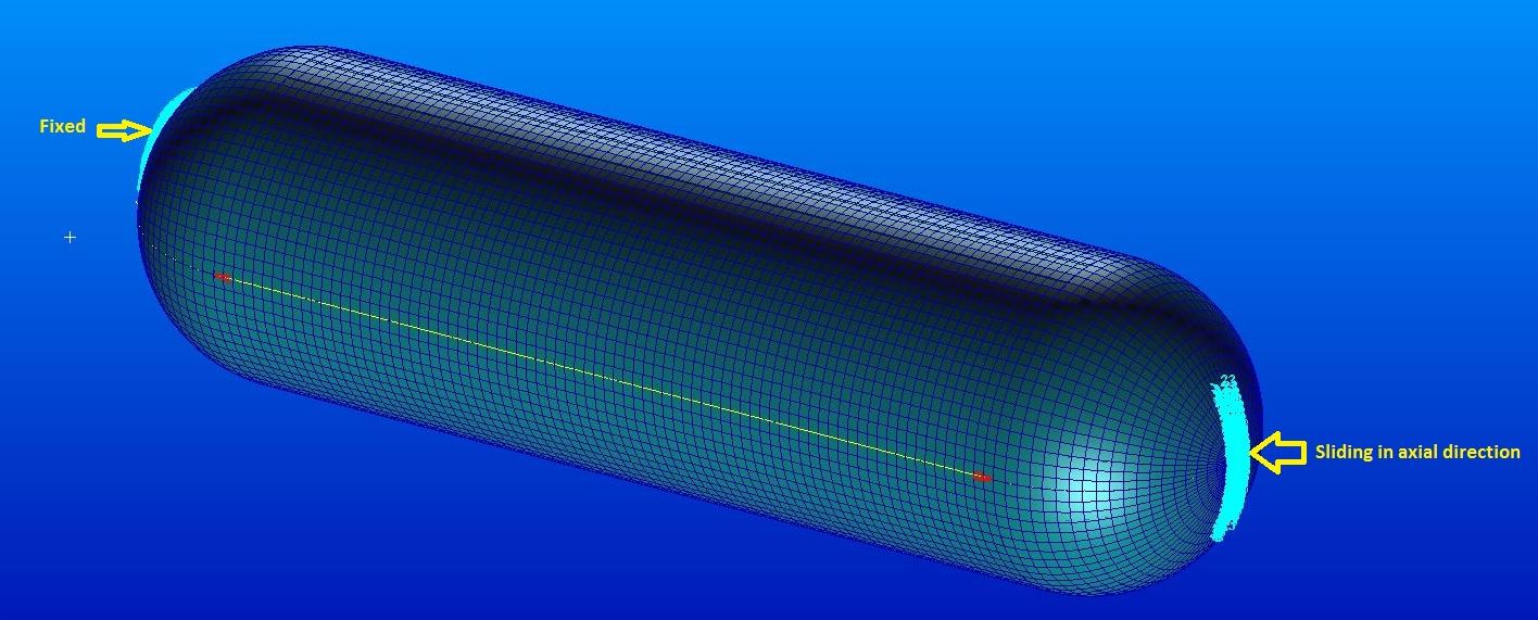
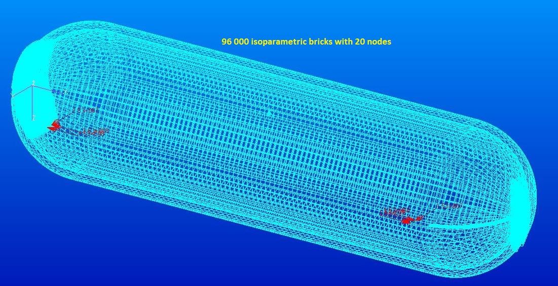
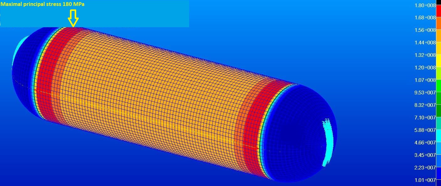
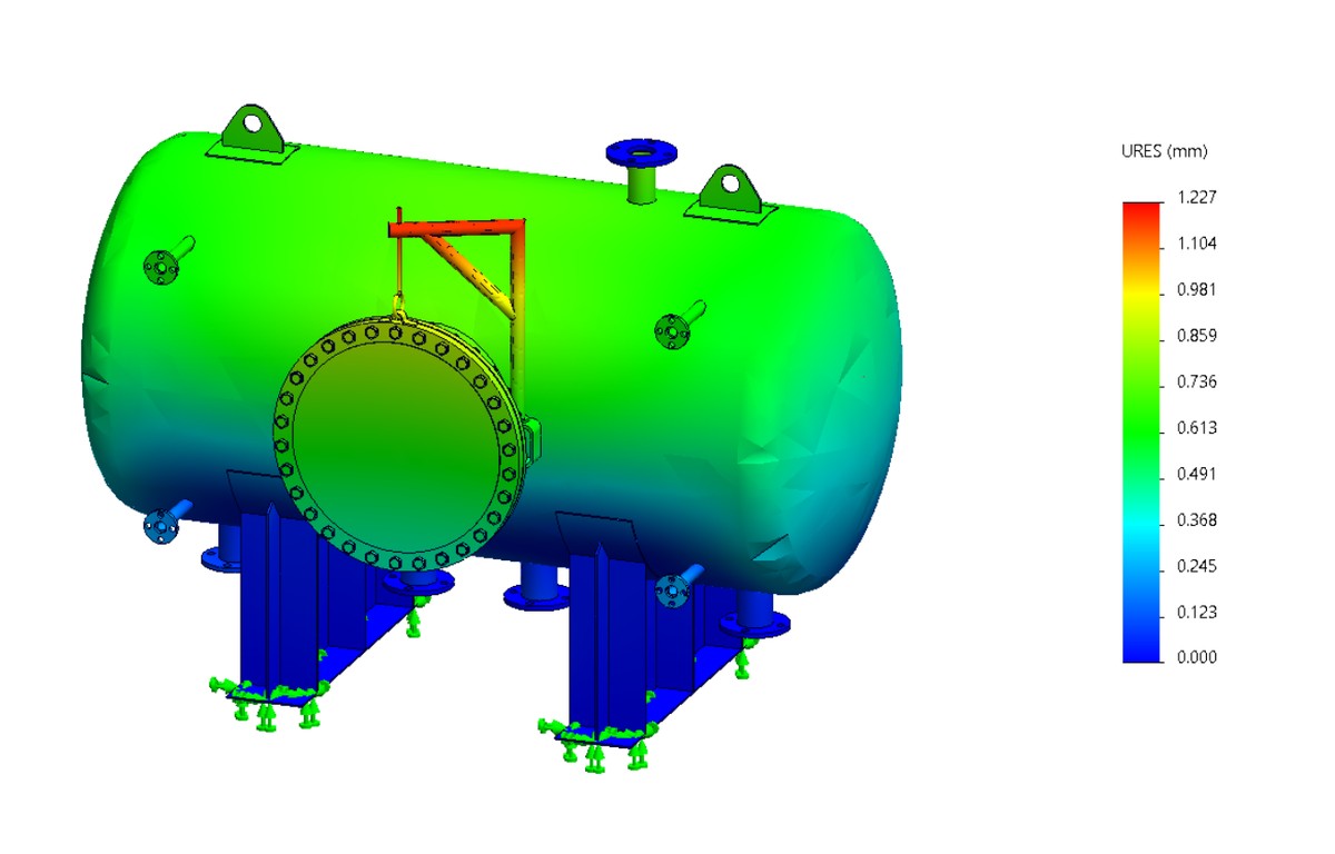
How a tank is analysed: supports, mesh, result
1 · Supports and loadsOne end fixed, the other free to slide axially, internal pressure on the shell.2 · Mesh96,000 quadratic brick elements, refined where the stress gradient is steep.3 · Stress resultMaximum principal stress peaks at 180 MPa near the head-to-shell junctions, then is checked against the allowable.
Illustrative curves of cyclonic separation — typical trends shown for demonstration, not measured client data.
Particle flow (DEM) for bulk solids handling
Discrete element simulation tracks every particle through your hopper, chute, conveyor or drum, so flow problems show up on screen rather than at commissioning.
Transfer chutes: spillage, impact zones, blockage and belt loading
Hoppers and silos: mass vs funnel flow, arching, discharge rate
Belt, screw and flap conveyors: capacity, carry-back and power
Rotary drums, roasters and mixers: bed motion, residence time, mixing index
Segregation by size or density, and liner wear prediction
Particle-to-structure loads handed straight to FEA
DEM: three particle layers carried off a belt into a transfer chute, coloured by starting layer to show mixing and segregation.
What you get
Calibrated material model from your product's angle of repose and bulk density
Videos and plots of flow, velocity and wear
Design changes tested in the model before fabrication
A heavy-equipment manufacturer needed a legacy pressure vessel redesigned for a higher operating pressure without increasing wall weight beyond shipping limits.
Method
Structural hand calculations set an initial wall-thickness envelope, followed by FEA to locate stress concentrations at nozzle penetrations.
Outcome
Delivered an ASME Section VIII-compliant design meeting the new pressure rating within the original weight budget.
Client identity withheld
Food & Dairy Processing Equipment
Cleanroom-grade stainless equipment designed to EHEDG hygienic principles, with clean-in-place flow verified by simulation before fabrication.
EHEDG-compliant radius welds and drainable geometry
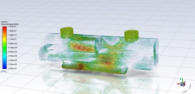
Clean-in-place (CIP) fluid flow simulation
Stainless material selection for wash-down environments
Sanitary fitting and seal specification
CFD velocity-vector plot — representative
CASE STUDY — ANONYMIZED
CIP-Verified Dairy Blending Vessel
The Challenge
A dairy processing equipment supplier needed a blending vessel that could pass CIP validation without disassembly, under EHEDG guidance.
Method
Redesigned internal geometry to eliminate flow shadows, then ran CFD on the CIP cycle to confirm full surface coverage and drainage.
Outcome
Delivered a drawing package with confirmed CIP coverage and zero low-flow dead zones, ready for hygienic certification.
Client identity withheld
Thermal Management & Heat Transfer
Industrial drying, baking, and thermal processing systems, engineered for tight spatial temperature uniformity and validated with instrumented prototypes.
A Netherlands-based industrial client required an energy-efficient thermal processing oven with strict internal spatial temperature uniformity under strict confidentiality.
Method
Performed convective and radiative heat transfer calculations, then CHT CFD modeling to optimize air distribution plenums and nozzle velocity profiles.
Validation
Built a physical prototype, installed calibrated multi-channel thermocouples, collected empirical thermal data, and confirmed CFD accuracy within a tight margin.
Outcome
Delivered a fully verified, code-compliant 2D/3D manufacturing drawing package with zero client identity exposure.
Client identity withheld
Custom Machinery & Special Projects
One-off and low-volume machinery where no off-the-shelf solution fits — from concept sketch through a working, verified machine.
Ground-up concept development for novel mechanisms
Multi-physics simulation for unconventional load cases
Rapid prototyping and iterative physical testing
Small-batch manufacturing drawing packages
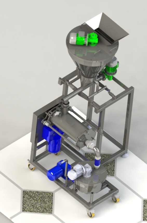
Custom process machinery — 3D concept render
CASE STUDY — ANONYMIZED
Purpose-Built Test Rig for a Novel Load Case
The Challenge
A specialty manufacturer needed a test rig to simulate a loading condition no standard equipment could reproduce.
Method
Developed a custom mechanism from first principles, validated the concept with FEA under the target load profile, then built and instrumented a working rig.
Outcome
Delivered a working test rig that reproduced the target load case within the client's required tolerance on the first build iteration.
Client: Indian process plant designer, for an EU operator · Scope: Hazardous-area classification, inerting basis, HAZOP/LOPA/SIL, explosion protection document, certification and handover
A sunflower lecithin de-oiling plant designed in India was to be installed and operated in the European Union. It uses two flammable solvents: hexane in dilution, filtration and evaporation, and acetone in batch extraction and solvent recovery. Fourteen process vessels, around 60 m³ in total, sit under a nitrogen blanket.
The plant had to meet the ATEX Equipment Directive 2014/34/EU and the Workplace Directive 1999/92/EC. The designer wanted as much of the plant as possible in Zone 2 rather than Zone 1, because every item moved from Category 2G to 3G cuts cost and lead time. That only holds if the case is engineered and written down: a nitrogen blanket alone does not make a vessel Zone 2.
Key challenges
Two solvents, one plantHexane and acetone loops with different release sources and operating modes.
Zone 2 inside inerted vesselsJustify the zone by how reliably the blanket is kept, how it fails and how fast failure is detected.
Designed in India, run in the EUEquipment, declarations and documents had to satisfy EU directives and inspectors.
Hidden air-ingress pathsVacuum duty and purging routes that could let air in faster than instruments react.
What we did
Worked from the P&IDs: every section reviewed line by line for release sources, ignition sources and air-ingress routes.
Classified hazardous areas to EN 60079-10-1, with a grade, ventilation basis and zone extent for every source. Governing group and class: IIA T3, set by hexane.
Built the inerting design basis to CEN/TR 15281: nitrogen supply and purity, oxygen limit, alarm and trip points.
Ran LOPA to IEC 61511: the result was a SIL 1 hardwired oxygen trip independent of the plant PLC.
Found the less obvious case: loss of vacuum lets air in faster than oxygen measurement can react, which would have needed SIL 2. An independent loss-of-vacuum alarm closed the gap at far lower cost.
Logged every decision: structured question rounds with the designer, with open assumptions flagged in the documents, not buried.
What we delivered
Explosion protection document in three parts (hexane, acetone, nitrogen blanketing)Hazardous-area classification report, zone list and source-of-release scheduleInerting design basis and explosion protection conceptHAZOP worksheet, LOPA, SIL determination and safety requirements specificationVentilation, static electricity and ignition-source assessmentsRelief, vent and flame-arrester basis; earthing, bonding and lightning protection basisEx equipment register and a zone and certification list for about 185 instrumentsVendor EU declaration of conformity reviews against 2014/34/EUOperating procedures for nitrogen purge, start-up and each solvent loopA 49-document handover structure with tracker, plus an interactive 3D process model
Result
Vessel interiors justified as Zone 2 under defined conditions: a proven SIL 1 oxygen trip, an independent loss-of-vacuum alarm, and a procedure that keeps in-vessel instruments safe until oxygen is confirmed low.
Equipment category reduced: instruments and valves inside blanketed vessels moved from Category 2G to 3G with a written basis; analysers and blanket transmitters needed during purging stayed 2G.
Problems found at design stage, not on site: the vacuum air-ingress scenario, fire-case venting gaps, missing drip trays, and vendor declarations citing the wrong standard or unsigned.
A complete, transparent document set: operator, designer and inspector work from the same basis.
Standards applied
ATEX 2014/34/EU1999/92/ECEN 60079-10-1EN 60079-14EN ISO 80079-36 / -37CEN/TR 15281IEC 61511IEC 60079-32-1EN ISO 4126-1
Building a plant that handles solvents or combustible dust?Talk to Norvik Systems about zoning and explosion protection before equipment is ordered.
Designing a Domestic Kitchen Appliance for an Indian Startup
Client: Confidential Indian startup · Scope: Requirement study, calculations, prototype, trials and testing, compliance-oriented design, engineering handover
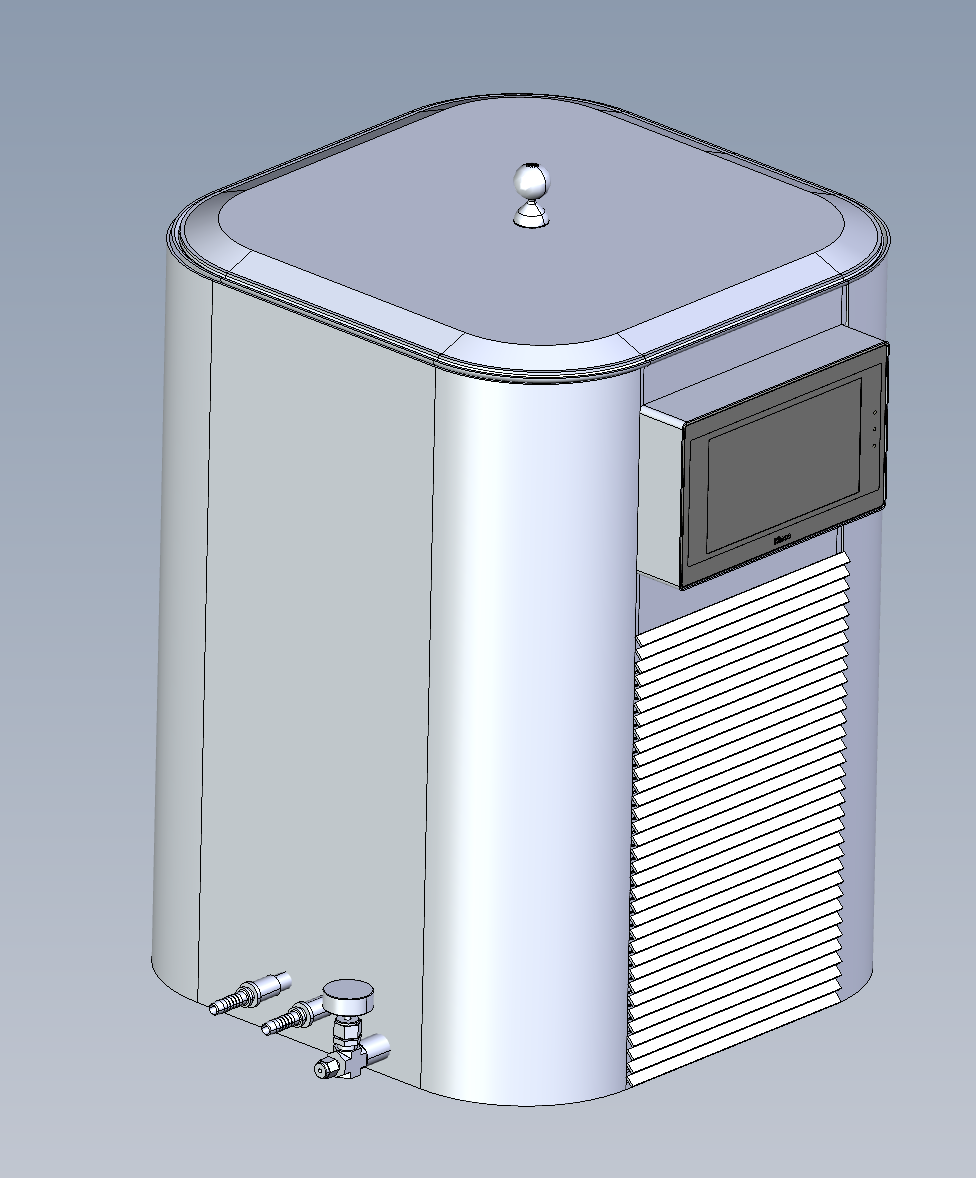
An Indian startup came to us with a new kitchen appliance concept. It had to perform reliably in a home kitchen, be safe for everyday users, and be ready for the certification an Indian domestic appliance needs. Norvik Systems took it from concept to a tested design, then handed over a complete engineering package.
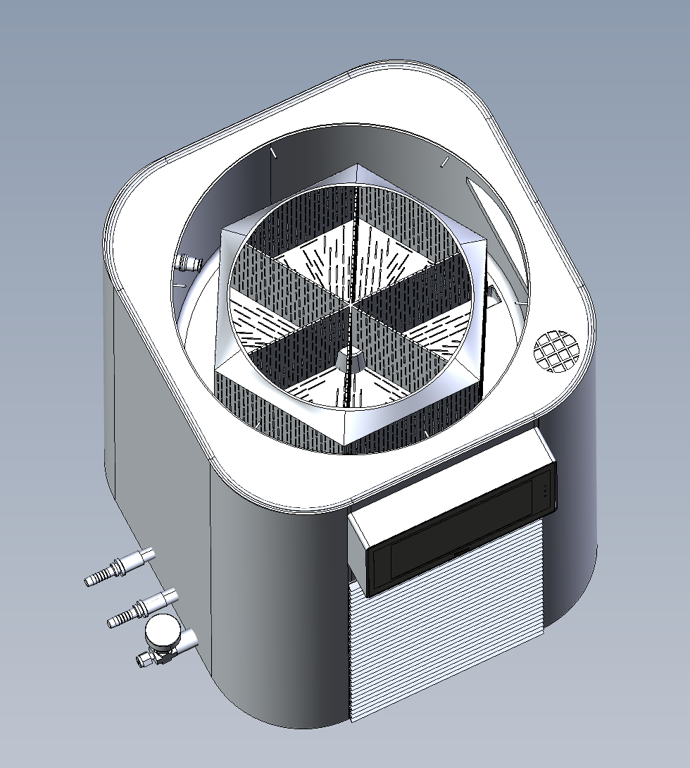
Internal layout: perforated, compartmented basket in a rounded housing.Final form: lid, touchscreen panel and ventilation louvres.
Key challenges
Consistent performanceRepeatable results across batch sizes and home operating conditions.
Home-use safetyProtection against electric shock, overheating and misuse.
Compact, kitchen-friendly formSmall footprint, easy loading, cleaning and access.
Startup pace and costDesign decisions had to be proven early to avoid costly tooling changes.
What we did
Understood the requirement: user needs, capacity, target performance and price point.
Calculated and designed: thermal, airflow and structural calculations; component sizing and layout.
Built prototypes: to test the design in real conditions.
Ran trials and testing: performance, temperature rise, repeatability and safety checks, with data recorded.
Refined the design: from test findings, before finalizing.
Handed over: drawings, calculations, test reports and documentation to support manufacturing and certification.
Designed for Indian compliance
Domestic electrical appliances in India are covered by BIS safety requirements under the IS 302 series, aligned with IEC 60335-1. We designed with these in mind from the start, so the startup was not forced into redesign at the certification stage.
Electrical safety: insulation, earthing and protection against shock.
Thermal safety: temperature limits on accessible surfaces and overheating protection.
Mechanical safety: stable structure, safe edges and access to moving or hot parts.
Food-contact materials: suitable materials and cleanable surfaces where the food touches the appliance.
Documentation: test records and design files organized for lab testing and BIS registration.
Certification is carried out by the product owner through BIS-recognized labs. Our design and test data are prepared to support it.
Result
A tested, design-frozen appliance ready for manufacturing
Design decisions backed by trial data, reducing the risk of late changes
A complete handover package the startup's team could take forward
Tested up to 100 cycles without failures.
Building a new appliance or product?Talk to Norvik Systems about designing it right before you tool up.
Custom Industrial Dryer: From Prototype to Full-Scale Design
Client: Confidential European manufacturer · Scope: Thermal design, prototype, sensor data, report, full-scale engineering and drafting
A European manufacturer needed a dryer that standard equipment could not provide. Before investing in a full-scale machine, they wanted proof that it would dry their product evenly. Norvik Systems designed and built an instrumented prototype, tested it, and used the data to design the full-scale dryer.
Key challenges
Product tiltingTilt controls product movement and exposure to air, so the angle had to be tested, not assumed.
Air velocity and directionSets heat transfer, bed penetration and fan energy.
Uniform flow across bed widthAir favors low-resistance paths; edges and center must dry alike.
Uniform drying across bed depthAir cools and picks up moisture as it rises, so layers dry at different rates unless controlled.
What we did
Understood the requirement: product, moisture targets, throughput and temperature limits.
Calculated and designed: mass and energy balance, psychrometrics, airflow and component sizing.
Built a prototype: with the bed, air path and tilt mechanism that drive performance.
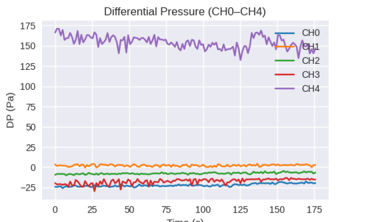
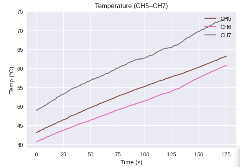
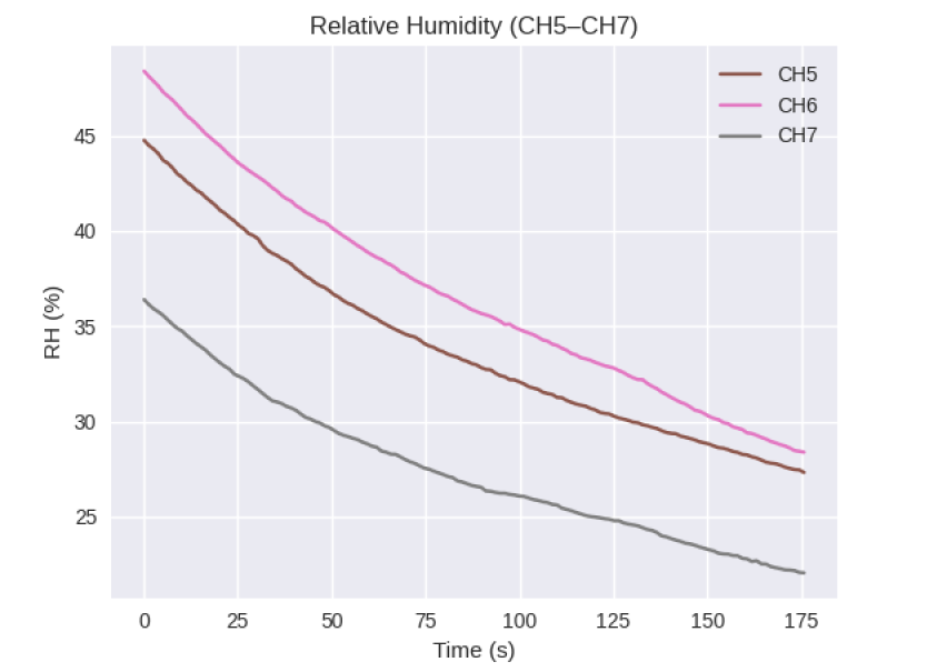
Instrumented and tested: sensors logged differential pressure, temperature and humidity.
Reported to the client: measured results against design, with scale-up recommendations.
Developed the full-scale dryer: design, drafting and calculations.
Prototype trial data
Live sensor logging across the prototype gave us a clear view of how the dryer behaves.
Differential pressure at five points. Readings were used to check airflow distribution and bed resistance.
Temperature rising steadily at three measurement points as the dryer heats up.Relative humidity falling at the same three points as drying progresses.
Why the client could invest with confidence
Tilt, airflow and uniformity were verified on a working prototype with real sensor data.
Deviations were found and fixed at prototype stage, where changes cost far less.
The client received a documented report to support the investment decision.
The full-scale design is based on measured data, not extrapolation.
Result
A validated, ready-to-build full-scale dryer design with complete calculations and drawings, with moisture variation within ±0.5% across bed depth.
Planning a drying or process equipment project?Talk to Norvik Systems about validating your design before you invest.